by Hans-Jürgen Euler, formerly of Leica Geosystems AG, Switzerland, now of inPosition, Switzerland, Euler@inPosition.ch
03 December 2005, some minor updates by Lambert Wanninger 11 December 2006 and 16 June 2008
Background
Over the last few years, permanent reference station installations have emerged in many countries. These installations allow for roving GPS users in the field to achieve centimetre accuracies without the need of setting up a GPS reference station on a known station.
This is quite appealing, since in areas with considerable GPS surveying activity, a number of users might share the infrastructure and the associated costs. Some of the installations are operated by companies and provide a service to the surveying community. Installations can be just single reference stations, a number of single reference stations, or networking reference stations. A single reference station set-up within up to 20-30 km is typically required if a user is operating in baseline mode. Otherwise the performance, accuracy, and with some systems the reliability of user's RTK is degraded.
The integration of several reference stations into a combined network provides benefits for the user by improving the accuracy and increasing the overall user system performance. For the reference station operator, networking reduces the number of stations that are needed to provide a given level of accuracy to the rover users. These permanent reference station networks are requiring real-time communication to a networking computation center and real-time estimation of biases between reference stations.
A key factor of success is the distribution of the information generated
within the networking computation center to the roving user in the field.
Some of the installations are relying on proprietary computation algorithms
and possibly formats and restricting themselves with the field equipment.
However, in general it is in the interest of service providers to supply
the service for more than a single type of RTK field equipment. Therefore,
the detailed understanding of the supplied information such as applied
corrections or the way of processing is absolutely mandatory.
Today, installations are supplying the information basically in two
ways: the so-called FKP-approach (FKP stands for the German word of spatial
correction parameter) and the VRS approach (Virtual Reference Station).
Both approaches deliver observations that are supposed to be operational
with modern RTK equipment. However, as noted above, the ways the computational
algorithms running at the networking computation center are proprietary.
Optimal interoperability is not guaranteed, since the definition and an
interface mechanism is missing. While the roving user equipment might work
optimally with one vendor's networking software providing a service, it
might have degraded performance with another vendor's software.
Independent RTCM Format
Traditionally, the communication interface between different manufacturer's GNSS equipment is the manufacturer independent RTCM format, which is jointly defined in a committee and all manufacturers have the possibility to participate in the definition discussions. Networking services based on either FKP or VRS approaches are providing the observations via the RTCM standard, but are basically operating in a mode not defined in the standard document and/or disseminating additional information in a proprietary message. RTCM delivers a container (message type 59) for proprietary information, but the content is not specified in the standard.
| Fig. 1: Schematic Sequence
of Processing |
However, the current networking approaches are distributing the principle
calculations between the software of the network and the rover. The arrows,
1 through 5, indicate possible interfaces that could be utilized for the
information transmission from the reference station network to the roving
user system. It should be mentioned that as long as calculation steps are
performed within the same software, these steps can be combined into one
step. This is actually done in some approaches. Some of the processing
steps prior to interfaces are easily described while others are quite sophisticated
and need a detailed description, since each step affects the remainder
of the processing chain. With the focus on interoperability between reference
stations software from one manufacturer and rover firmware from another,
these processing steps become very important for best rover performance
in general. The first two interfaces, 1 and 2, are quite easily described.
Through the first, the raw observations of all reference stations are transferred.
Within the second schematic box the main calculations for fixing and removing
the so-called integer ambiguities are summarized. Through the interface
afterwards basically the raw observations levelled to a common integer
ambiguity level are transferred to the next calculation step. The next
three interfaces are carrying information modified by algorithms of the
previous boxes and need detailed descriptions. In order to keep the computational
burden low on the roving user system the most logical interface is 2, since
the network has already resolved the integer ambiguities between reference
stations. The remainder of the calculations can be optimized within one
software, the roving user's firmware.
Master-Auxiliary Concept
Within RTCM Special Committee No. 104 (SC104), a Network RTK working group is developing the future standardized way of interfacing between networking reference stations and roving field users. Interface 2 as described above has been identified and proposed as the most common ground between all vendors. After the initial proposal in 2001, the Network RTK messages of RTCM are being jointly discussed with other vendors and a consensus on the concept has been reached. The basic idea of this so-called Master-Auxiliary Concept is to use one Master Reference Station and its raw data stream such as RTCM V3.0 message type 1004 (RTCM, 2004) and reduced information of other Auxiliary Reference Stations in the vicinity of the field of rover operation.
The Master-Auxiliary concept uses so-called dispersive and non-dispersive phase correction differences to compress network RTK information without the need for standardized correction models (Euler et al., 2001 and Zebhauser et al., 2002).
The description of correction differences begins with the following
definition of the single difference L1 phase equation ![]() between two stations k, m and satellite j
between two stations k, m and satellite j
| (Eq. 1) | 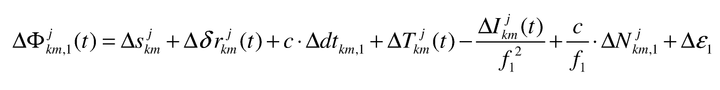 |
where
| geometric range term including antenna phase centre variations which have been applied by the network processing software, | |
| broadcast orbit error, | |
| receiver clock error, | |
| tropospheric refraction error, | |
| frequency dependent ionospheric delay, | |
| frequency dependent integer ambiguity, | |
| frequency dependent random measurement error, | |
| epoch, | |
| speed of light, | |
| frequency of L1. |
An analogous equation for the L2 single difference phase equation can be written by replacing the index of the frequency dependent terms with 2.
Correction differences are formed by subtracting the ambiguity-leveled
phase corrections of a designated master reference station from the equivalent
corrections of the remaining, or auxiliary, reference stations in the network
such that
| (Eq. 2) | 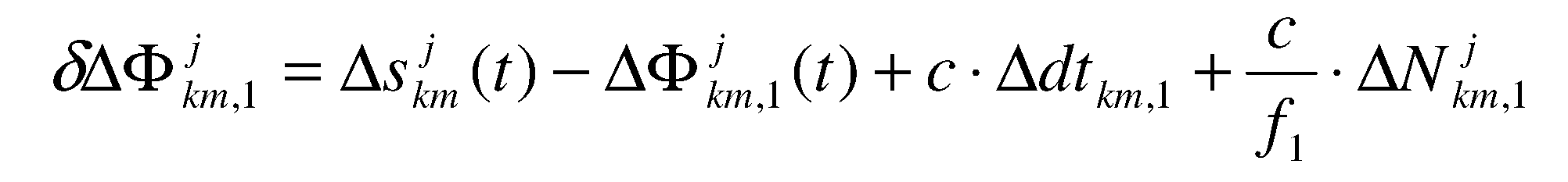 |
The generation of the integer ambiguity level, a key feature of Master-Auxiliary concept, is detailed in Euler et al. (2001).
To further reduce the amount of data transmitted to the rover, Eq. 2
can be separated into a dispersive component, consisting mainly of ionospheric
refraction, and a non-dispersive component consisting primarily of tropospheric
refraction and orbit errors. The dispersive and non-dispersive correction
differences are given by
| (Eq. 3) | 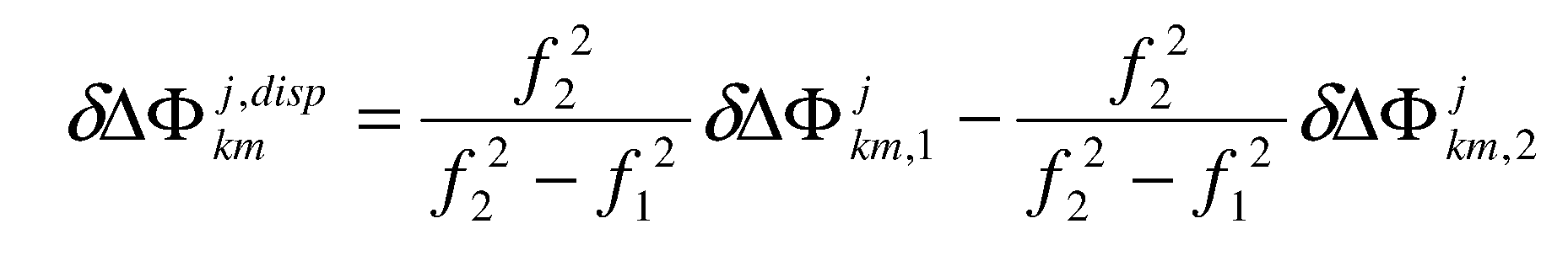 |
| (Eq. 4) | 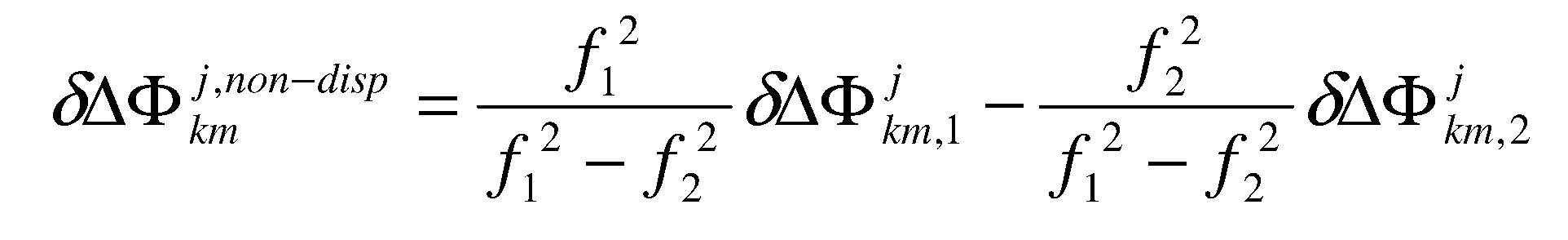 |
This alternate representation of the correction differences has some specific benefits. Unlike the correction differences described in Eq. 2, the dispersive and non-dispersive components vary at different rates. In general, non-dispersive errors change slowly over time, while dispersive errors vary more rapidly, especially in times of high ionospheric activity. Therefore, optimizing the transmission rates of the dispersive and non-dispersive components can maximize data-link throughput.
In addition to the correction differences, the raw carrier phase information
for the master reference station, described via RTCM V3.1 standard messages
(RTCM, 2006), must also be streamed to the rover. Using the phase data
of the master station and the correction differences, the rover can re-assemble
and apply the raw phase information of the auxiliary stations in conventional
baseline processing schemes. Alternatively, optimal correction differences
can be interpolated for any position in the network and used to correct
rover data. Interpolation of the correction differences is possible because
they share a common integer ambiguity level. Since the raw observations
of the master reference station are being part of the disseminated data
stream, equipment without knowledge how to use the network RTK can also
operate in a normal baseline mode.
Network Subnetworks
Shown in figure 2 is the main aim of permanent reference station network
software: the collection of data at a central location and the elimination
of integer ambiguities between the reference stations. Many different interpretations
of the term network are possible. The following description of network
and subnetwork are based on the current RTCM definitions. A network is
defined as the total structure of reference stations to be brought to the
same ambiguity level in a consistent solution. If the overall assembly
of the reference stations does not allow a consistent solution (all reference
station on the same ambiguity level) on a regular basis, several subnetworks
with possibly inconsistent solutions have to be defined. A network shall
have in general only one subnetwork. The introduced Subnetwork ID is an
automatically generated number.
Fig.2: Master-Auxiliary Concept
All Master Reference Stations and also all involved Auxiliary Reference Stations with an identical Network ID and an identical Subnetwork ID are on the same integer ambiguity level. A common integer ambiguity level for several stations indicates for the rover operation that data information streams are interchangeable for these reference stations without reinitializing fixed rover integer ambiguities.
As soon as a reference station network solution breaks apart and a complete
new set of integer ambiguities has to be calculated, the Subnetwork ID
has to be increased. The increased Subnetwork ID indicates to the rover
that something happened to the network integer ambiguities and the rover
has to take proper action. Sometimes it might happen that a homogenous
integer ambiguity level is not achievable for the entire network. This
might be the case during start-up of the network solution or when reference
stations crucial for the whole network are no longer available. Under these
circumstances the network solution might be provided under one Network
ID and each separated homogenous solution with identical integer ambiguity
level will have assigned different Subnetwork IDs. The rover shall check
the Subnetwork IDs in the messages provided and it will combine only information
with identical Subnetwork IDs.
Throughput Requirements
The Master-Auxiliary Concept sends additional information and needs
more throughput than a transmission in pure single reference station mode.
In comparison to other similar methods the new RTCM V3.1 standard is quite
compact. It provides a reduction of throughput of about 70% as compared
to the older version 2.3. With the Master-Auxiliary Concept additional
information on the network structure is transmitted which is missing in
the other approaches. The throughput is varying with the chosen update
rates of the different required messages. With reasonable numbers such
as up to 12 visible satellites and 7 to 9 reference stations involved,
the amount of data to be transferred to the field system takes between
2800 and 3200 bits per second. This number has to be compared to numbers
of 4500 bits per second raw observation information transmitted for 1 reference
station for 12 satellites with the more bulky RTCM standard V2.3.
Summary
Within RTCM SC104 a working group is developing a standardized method to transfer network RTK information from a processing center to a rover operating in the field. The proposed interface is currently under interoperability testing with participation of several vendors.
After the release of this standard, network RTK will be completely interoperable for the first time. Then, networking software developed by different vendors can produce identical output data streams from identical input data. Rovers in the field can operate optimally and their performance is no longer dependent on the actual networking software. The rover receives information about the distribution of reference stations and optimization can be performed in real-time by the rover system.
According to the Master-Auxiliary Concept, not only the original raw observations for the Master Station are sent to the rover but also correction differences of the Auxiliary Stations. The rover system can decide to use or to neglect the network RTK information depending on its own firmware algorithm performance.
References
Euler, H.-J., Keenan, C.R., Zebhauser, B. E., Wübbena, G. (2001): Study of a Simplified Approach in Utilizing Information from Permanent Reference Station Arrays, ION GPS 2001, September 11-14, 2001, Salt Lake City, UT (download page: PDF file, 674 kB)
Euler, H.-J., Zelzer, O., Takac, F., Zebhauser, B.E. (2003): Applicability of Standardized Network RTK Messages for Surveying Rovers, ION GPS/GNSS 2003, September 9-12, 2003, Portland OR (download page: PDF file, 1 MB)
Euler, H.-J., Seeger,St., Zelzer, O., Takac, F., Zebhauser, B.E. (2004): Improvement of Positioning Performance Using Standardized Network RTK Messages, ION NTM, January 26-28, 2004, San Diego, CA (download page: PDF file, 604 kB)
RTCM (2006): RTCM Recommended Standards for Differential GNSS (Global Navigation Satellite Systems) Service, Version 3.1, RTCM Standard 10403.1 (RTCM webpage)
Wanninger, L. (2004): Introduction to Network RTK. IAG Working Group 4.5.1: Network RTK (HTML file, 153 kB)
Zebhauser, B. E., Euler, H.-J., Keenan, C.R., Wübbena, G. (2002): A Novel Approach for the Use of Information from Reference Station Networks Conforming to RTCM V2.3 and Future V3.0, January 28-30, 2002, San Diego, CA.